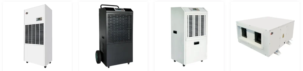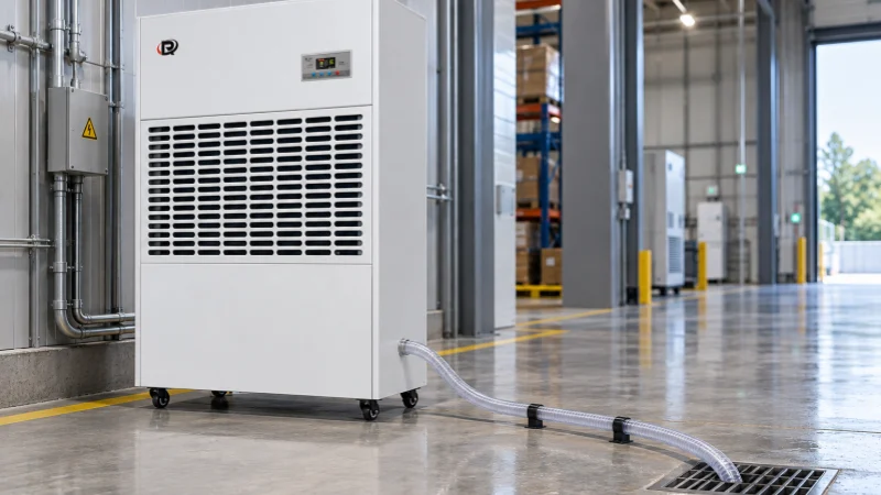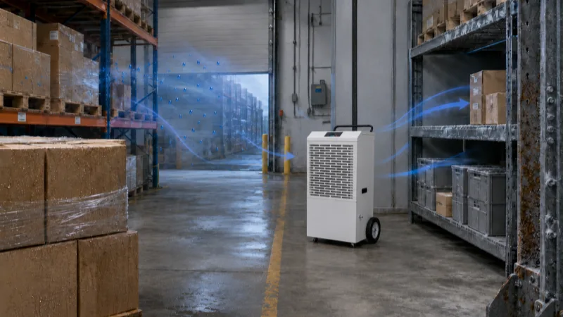
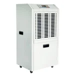
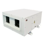
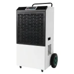
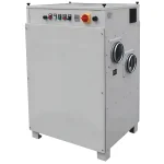
A warehouse operator wants to dry the air while keeping stored goods at 22°C. A dehumidifier can meet the humidity target and still blow warm air across the racks. Before approving the unit, the operator needs to know whether the existing cooling coil can carry away that heat.
This guide shows how to estimate the heat a dehumidifier adds and check it against the cooling available in the room. When a refrigerant dehumidifier returns warm, dry air to the warehouse, the air conditioner has two different jobs to check. It must remove more heat to hold 22°C, but it has less moisture to remove if the dehumidifier takes over drying already included in the load for that hour. That is why a coil can have enough total capacity and still let the room get too warm.
Trace where the heat goes
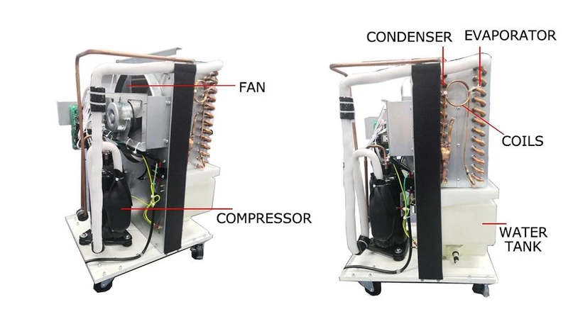
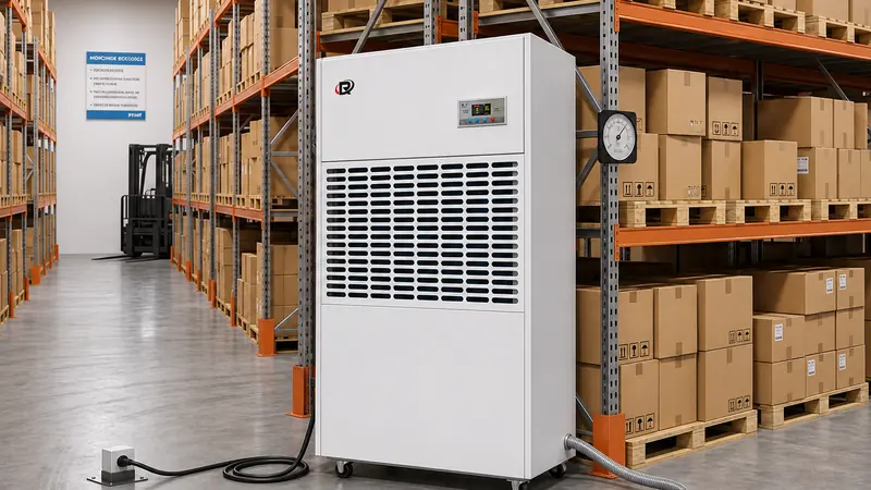
When comparing industrial dehumidifier configurations, trace two paths on the drawing. Where does the dry air go, and where does the condenser release heat? The cabinet can sit in a mechanical room while the supply duct carries most of the heat to a temperature-controlled store.
In a self-contained refrigerant unit, the cold coil (evaporator) cools the air and condenses water. The condenser releases the heat absorbed at the evaporator plus the work supplied by the compressor. With full indoor reheat, both coils act on the same air stream. Part of the condenser’s output simply brings the air back up to its inlet temperature. Using the condenser rating alone would therefore overstate how much warmer the unit makes the returning air.
Units with partial reheat can divert some heat to another condenser, which changes the temperature of the air returning to the room.
Calculate sensible heat output at the room’s operating conditions
Sensible heat is the heat that raises the air temperature. For a steady-running refrigerant unit with full indoor reheat, use sensible gain (kW) ≈ whole-unit input (kW) + water removal (kg/h) × 0.68 (kWh/kg). The factor approximates the heat released when a kilogram of water vapor condenses near room temperature. This estimate applies when both coils and the unit’s heat losses are in the zone being evaluated. Liquid water carries a small amount of energy away through the drain. The estimate omits that correction. For a detailed energy balance, use the liquid’s enthalpy at drain temperature with the same reference used for the air.
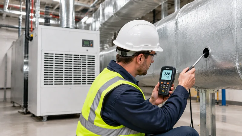
If a unit in a separate mechanical room recirculates warehouse air, measure the return and supply temperatures and airflows where the ducts cross the warehouse boundary. For balanced flow, the airflow and supply-to-return temperature difference give the sensible heat delivered to the warehouse. Those readings already reflect heat exchanged along the ducts. Account separately for any leakage, replacement air and cabinet heat in the zones they affect.
When sizing an industrial dehumidifier, establish the required removal rate at the design inlet conditions. For the heat estimate, take actual removal and running power from the same operating point on the proposed model’s performance sheet. If a supplier gives liters per day for continuous operation at that point, divide by 24 to get liters per hour. A liter of condensate weighs approximately one kilogram. For a US schedule, multiply the result in kW by 3,412 to obtain Btu/h. Ask which fans, controls and pumps the quoted input includes. Count each electrical load once and assign its heat to the zone where it is released.
In a Florida Solar Energy Center lab test, researchers ran one ducted residential unit at a steady 165 cfm. With inlet air at 82.8°F and 57.3% relative humidity (RH), it drew 581 W, removed 3,458 Btu/h of latent heat and delivered 5,041 Btu/h of sensible heat. At 75.7°F and 49.1% RH, the same readings were 516 W, 2,289 Btu/h and 3,661 Btu/h. Those residential measurements show how inlet conditions affect one machine. Use the industrial model’s own performance data for its cooling allowance.
Which moisture belongs in the cooling load?
The calculation above gives the extra sensible cooling duty. Latent cooling is the work of removing water vapor. Before reducing the air conditioner’s latent load, check which moisture sources the original calculation assigned to it. A loading door, a wet floor and a pool can all add water vapor, but they bring different loads into the calculation.
| Moisture source | What to enter for the design hour |
|---|---|
| Humid outdoor air entering through a loading door | Include the moisture carried in through the open door. If the building also supplies treated outdoor air through ducts, calculate that separate contribution using the air conditions after treatment. |
| A wet floor or product drying indoors | Evaporation draws heat from the surface and its surroundings. Account for that cooling where it occurs and for the resulting vapor where it is removed. Keep temporary dry-out separate from normal storage. |
| An indoor swimming pool | Evaporation takes heat from the pool water and adds moisture to the hall air. Track the pool-heating duty separately. Credit condenser heat returned to the water only during hours the pool can accept it. |
If the original calculation omitted a moisture source, correct the baseline before subtracting latent duty. Otherwise the worksheet gives the cooling coil credit for work it was never expected to do.
Put the change into the cooling load sheet
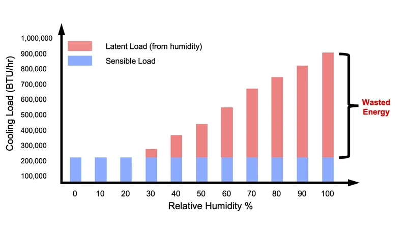
Return to the warehouse with the 22°C storage target. Assume the air enters the unit at that temperature and 60% RH. The proposed recirculating unit removes 2.5 kg/h and draws 1.8 kW while running at those conditions. The original design hour includes 8.0 kW of sensible load and 3.0 kW of latent load. In this example, the same air conditioner would have handled all 3.0 kW of latent load during that hour. The moisture sources stay the same, and the dehumidifier takes over 1.7 kW of that duty.
The water removal accounts for 2.5 × 0.68 = 1.7 kW. Adding 1.8 kW of electrical input gives 3.5 kW of sensible heat, or about 11,900 Btu/h. Enter those changes on separate lines for the same hour.
| Room load | Before | Change while drying | Revised duty |
|---|---|---|---|
| Sensible cooling | 8.0 kW | +3.5 kW from the unit | 11.5 kW |
| Latent cooling | 3.0 kW | −1.7 kW taken over by the unit | 1.3 kW |
| Total cooling | 11.0 kW | +1.8 kW | 12.8 kW |
The coil now needs 11.5 kW of sensible capacity. Suppose the air conditioner’s performance sheet shows 13.0 kW total and 10.5 kW sensible at the revised inlet conditions, design airflow and outdoor temperature. It clears the 12.8 kW total duty. Its 10.5 kW sensible capacity still leaves a 1.0 kW shortfall against the 11.5 kW needed to hold 22°C. Ask the designer to check another coil operating point or a configuration that rejects part of the heat outside the room.
Check the temperature at the discharge
Suppose the unit in this example delivers 1,000 m³/h and all 3.5 kW of sensible gain reaches that airstream. Near room temperature and sea-level pressure, the inlet-to-outlet rise is approximately 3.5 ÷ (0.000335 × 1,000) = 10.4°C. Air entering at 22°C would therefore leave at about 32.4°C before it mixes with room air. Check where that jet goes if a rack holds temperature-sensitive stock or a nearby sensor controls the cooling.
The coefficient combines air density (about 1.2 kg/m³), specific heat (about 1.005 kJ/kg·K) and the conversion from hours to seconds. For an installed unit, use measured or manufacturer-supplied air-side sensible output at the installed airflow. Heat released from the cabinet into the room belongs in the room load but contributes nothing to this outlet-temperature estimate.
If the warm discharge joins the air conditioner’s supply duct after the cooling coil, estimate the mixed supply temperature by weighting each stream’s temperature by its share of the total air mass flow. For example, if the coil supplies three quarters of the mass flow at 14°C and the dehumidifier supplies one quarter at 32.4°C, the mixture is about 18.6°C. This assumes complete mixing, similar specific heats and negligible heat exchange along the duct. If the two streams meet before the cooling coil, use the mixed conditions at the coil inlet when checking its capacity.
What changes if the heat goes elsewhere?
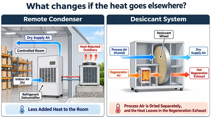
If a coil falls short on sensible capacity, ask where the dehumidifier can release heat. A remote condenser can move some duty out of the room. A desiccant system requires a different calculation because the dried supply air and the hot regeneration exhaust follow separate paths.
| Configuration | Supply air | What to verify |
|---|---|---|
| Full indoor reheat | Warmer than the inlet while drying | Same-zone sensible gain at the design operating point. |
| Remote condenser with partial or no reheat | Cooler than with full reheat. It may supply sensible cooling. | Leaving temperature and airflow in each mode at the design outdoor temperature. |
| Water-cooled condenser or pool heat recovery | Depends on how much heat returns to the air | Air outlet temperature, water flow and temperatures, and where heat goes when the water loop cannot accept it. |
| Industrial desiccant dehumidifier | The wheel warms the dried process air. A downstream coil can cool it to the supply target. | Process outlet temperature and airflow at the required moisture level. Check regeneration exhaust and any replacement air separately. |
Check when drying and cooling run together
The toughest temperature check may come after the shift ends. In a store beside a washdown area, moisture may continue entering after the cooling plant switches to its night schedule. Check how many drying units can run together, what cooling is available then, and whether that operating mode holds the specified room temperature. An average daily run time can hide an hour when every unit is on and cooling is unavailable. In a grow room, check the lights-off period separately. Lighting heat falls as soon as the lights switch off, while plants can continue releasing moisture.
What to request before approving the equipment
A room-recirculating unit with full indoor reheat can be screened using water removal and running power at the design inlet conditions. For partial or remote heat rejection, water cooling, heat recovery or a desiccant wheel, those two figures alone cannot establish room heat gain. Before purchase, request model-specific air-side performance for each mode that can run during the design hour. For a cabinet outside the target room, also check the airflow and temperature expected at the room grille.
| Supplier data | Decision it supports |
|---|---|
| Water removed and whole-unit running power at the same inlet conditions | Calculate latent duty taken over and sensible heat returned with full indoor reheat. |
| Installed airflow, outlet temperature and air-side sensible output | Determine the heat carried through the duct into the controlled room. |
| Indoor, outdoor or water-side heat rejection by operating mode | Check the highest coincident room load and whether the receiving heat sink can accept it. |
Frequently asked questions
How much will the room temperature rise?
Outlet temperature alone cannot predict the room temperature rise. Room temperature depends on the heat exchanged with adjacent spaces and outdoors, the cooling delivered and the duration of operation. Use a representative room sensor away from the discharge jet to verify the result.
Can I vent a dehumidifier’s warm air outdoors?
Exhausting the dry supply also discards the air the unit just dried. Replacement outdoor air can bring moisture back into the building. If the project needs indoor drying and outdoor heat rejection, ask for a configuration with a separate condenser heat path.
Can the dehumidifier count toward winter heating capacity?
A dehumidifier can offset some heating demand while its humidity control calls for drying. A cold, dry room can need heat with the dehumidifier idle, so check the heating system against that condition before crediting any recovered heat.
Can I use a condensate meter to check the heat estimate?
Yes, as a first estimate for a full-reheat unit in the same conditioned space. Over a steady running interval, record inlet temperature and RH, then divide collected kilograms and metered kWh by elapsed hours to obtain kg/h and average kW. To verify the sensible heat carried by the air, measure airflow and the temperature difference across the unit.
Before you approve the unit
In the warehouse example, the coil has 0.2 kW of total capacity to spare yet falls 1.0 kW short on temperature control. For a warehouse humidity-control project, send Rinwang the target temperature and RH, expected moisture load, unit location and cooling schedule. Ask for the proposed unit’s performance at those conditions so your HVAC designer can check the sensible capacity available during the same hour.