A crawl space dehumidifier can be correctly sized and still perform poorly after installation. Common problems include short-circuiting airflow, humid pockets behind foundation walls, blocked drains, inaccessible filters, poorly located sensors and equipment operating outside its intended temperature range.
For contractors, a successful installation depends on more than placing the unit in the crawl space and setting the humidistat. The moisture boundary, equipment location, air distribution, drainage, electrical supply and commissioning process all affect whether the system can maintain stable conditions after the job is complete.
This guide focuses on how to install and commission a crawl space dehumidifier so that the selected equipment can perform as intended and future callbacks are easier to prevent and diagnose.
Confirm the Crawl Space Is Ready for Dehumidification
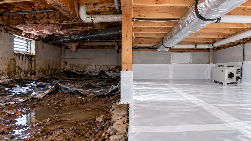
A dehumidifier should control residual airborne moisture, not compensate for active water problems. Before installation, inspect the crawl space for standing water, plumbing leaks, groundwater entry, roof or grading problems, open sumps and other sources of bulk water.
The enclosure also needs to match the intended moisture-control strategy. Where the project uses an encapsulated or unvented crawl space, check that the vapor retarder, seams, wall terminations, access doors, vents and service penetrations have been completed as specified. The 2024 IRC requirements for unvented crawl spaces include a continuous Class I vapor retarder over exposed earth, while the exact project requirements still depend on the adopted code and local amendments.
Recent water remediation or wet framing can also create a temporary drying load that is much higher than the long-term maintenance condition. That initial moisture should be distinguished from the permanent operating requirement before the installation is judged.
If capacity has not yet been established, complete the crawl space dehumidifier sizing before installation. The expected operating condition, required capacity and basic airflow strategy should already be defined before the contractor plans the final equipment position, drainage and electrical connections.
Verify the Selected Unit Before It Goes Into the Space
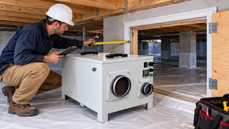
Before moving the selected crawl space dehumidifier into position, confirm that it matches the expected operating temperature, airflow arrangement, drainage method, electrical supply and available service space.
Review the minimum operating temperature, defrost method, airflow, available external static pressure for ducted layouts, condensate connection, electrical requirements and service clearances. If the crawl space is divided into several bays, also confirm whether the design assumes free-air operation, ducting or multiple units.
Access dimensions should be checked before installation begins. A unit that cannot pass through the access opening, rotate around foundation piers or leave enough clearance for future panel removal is not a practical choice even if its nominal capacity is correct.
The purpose of this step is not to repeat the sizing calculation. It is to verify that the unit arriving on site is the same equipment the installation was designed around.
Choose the Installation Location Around Airflow and Service Access
The geometric center of the crawl space is not automatically the best location. A slightly off-center position may perform better if it provides a clear intake path, directs dry air into the longest open section, allows reliable drainage and leaves enough room for future service.
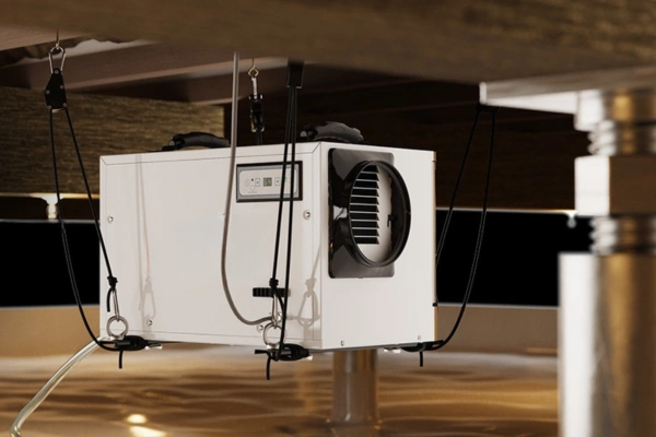
The unit should be placed on stable support, protected from standing water and installed in the orientation permitted by the manufacturer. Filters, access panels, controls, electrical compartments, condensate connections and removable components should remain accessible after the job is complete.
Avoid locations where the discharge immediately returns to the intake. This short-circuiting can create an artificially dry condition around the dehumidifier while remote areas remain humid. The control sensor may then satisfy the setpoint even though only part of the crawl space is actually being treated.
Service access should be considered at the same time as airflow. If a filter cannot be removed without disturbing ductwork, or a drain connection is hidden behind framing, routine maintenance becomes harder and small faults are more likely to turn into callbacks.
Plan Air Distribution Through the Entire Crawl Space
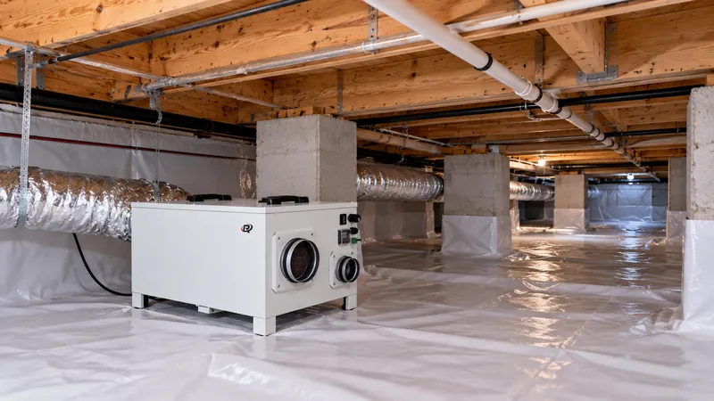
Moisture-removal capacity only helps where dry air can reach. Open crawl spaces with few obstructions may be served by one free-air unit when the intake and discharge have a clear path through the controlled area. Foundation walls, piers, additions, mechanical services and narrow passages can change that quickly.
Where airflow is restricted, the installation may need supply ducting, return ducting, transfer openings or multiple units. Ducting is especially useful when the equipment would otherwise recirculate its own discharge or when dry air needs to reach a remote section that cannot be served effectively by free discharge.
Duct design should not be based only on the unit’s free-air CFM. Once ducts, bends, grilles and fittings are added, external static pressure increases and delivered airflow can fall. The final arrangement should therefore remain within the manufacturer’s fan curve or approved duct limits.
Sensor location should follow the same logic. A humidistat mounted directly in the discharge path can shut the unit off before the rest of the crawl space reaches the target condition. Place the control sensor where it represents the general crawl-space condition, and use additional verification points where the space is large, divided or irregular.
Build the Condensate Drain for Unattended Operation
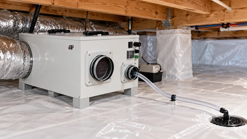
A crawl space dehumidifier may operate for long periods without anyone entering the space, so the condensate system needs to be reliable enough for unattended operation.
Use gravity drainage only where the full route can maintain the required fall to an approved discharge point. Avoid low spots, sagging tubing, crushed hoses, blocked terminations and concealed joints that cannot be inspected. The route should also be protected from physical damage and, where relevant, freezing.
When gravity drainage is not practical, use a condensate pump that can handle the required vertical lift and horizontal run. The final dehumidifier drainage layout should account for drain slope, pump limits, overflow protection, accessible joints and the location of the final discharge point.
After installation, test the drain rather than simply inspecting it visually. Confirm that water moves through the entire route, that pump operation is reliable, that joints do not leak and that any high-level or overflow protection functions correctly.
Complete Electrical and Control Connections Properly
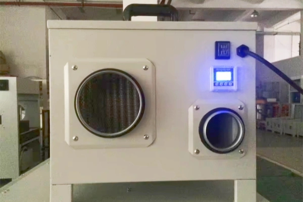
The electrical supply should match the equipment nameplate for voltage, phase, frequency and current. The responsible electrician should determine conductor sizing, circuit protection, disconnecting means, receptacle requirements and any ground-fault protection required by the adopted electrical code and site conditions.
Extension cords should not be used as the permanent supply. NFPA materials similarly state that extension cords are not a substitute for permanent wiring and should not be routed through walls, floors or other locations where they may be damaged.
Wiring, plugs, controls and junctions should also be routed away from water paths and protected from abrasion or service damage. Where the dehumidifier supports external humidistats, alarms, remote contacts or building-management integration, test those connections during commissioning rather than assuming communication is working because the unit itself operates.
For unattended crawl spaces, automatic restart after a power interruption can also be important. A machine that remains off after an outage may create a hidden failure that is not noticed until humidity rises again.
Commission the Installation Before Handover
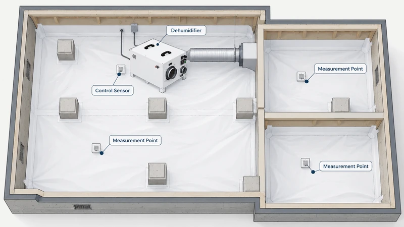
Startup confirms that the equipment runs. Commissioning confirms that the complete installation works.
Begin by comparing the control sensor with field hygrometers so later readings can be trusted. Record baseline temperature and RH in representative parts of the crawl space before the system has had time to change the condition. EPA guidance recommends keeping indoor RH below 60%, ideally between 30% and 50% where practical, although the final crawl-space setpoint should still follow the project design rather than being treated as a universal code value.
Once the unit is operating, verify that the intake is unobstructed, the discharge airflow is moving in the intended direction and remote sections are receiving air. If ducting is used, check that airflow remains adequate at the distant outlets and that there is a return path back to the unit.
The condensate route should be tested under operating conditions, including pump operation where applicable. Controls should also be checked for setpoint response, restart after power interruption, alarm behavior and any remote-monitoring functions included in the project.
Do not judge the installation from a rapid RH drop beside the machine. Allow the crawl space and any previously damp materials time to stabilize, then review temperature and RH trends from representative locations. A successful installation should show that the whole controlled zone is moving toward the required condition rather than only the air immediately around the unit.
The handover record should include the final setpoint, sensor locations, filter information, drain route, electrical circuit, equipment location and maintenance requirements. Photographs of the completed installation can also make future service and troubleshooting easier.
Diagnose Callbacks Before Replacing the Unit
When a contractor receives a callback, the first assumption is often that the dehumidifier is too small. In practice, many crawl space problems are caused by the moisture boundary, airflow, drainage, sensor placement or operating conditions rather than insufficient nominal capacity.
| Callback symptom | First checks | Likely response |
|---|---|---|
| RH never reaches setpoint | Sensor location, leaks, open vents, actual intake condition | Correct the moisture source or verify the original selection |
| One bay stays humid | Foundation obstructions, short-circuiting, blocked air path | Reposition, duct or divide the space |
| Coil repeatedly frosts | Intake temperature, dirty filter, airflow, defrost operation | Correct airflow/defrost or verify low-temperature suitability |
| Water appears on the liner | Drain slope, blocked hose, pump lift, outlet condition | Repair and retest the condensate route |
| Unit cycles too frequently | Sensor position, control differential, local recirculation | Correct the sensor or airflow layout |
| RH appears acceptable but condensation remains | Dew point, cold surface temperature, insulation, stagnant air | Improve local conditions or lower the space dew point |
A useful diagnostic order is to verify the measurement first, then the moisture boundary, actual operating condition, airflow, drainage, equipment and controls. Increasing capacity should come only after those factors have been checked.
This approach helps separate a genuine equipment limitation from a problem created by the installation around it.
When One Unit Is Not Enough
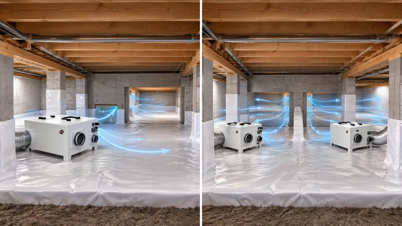
A single unit is not always the best answer for a large or divided crawl space. Several smaller units may provide better distribution where foundation walls create separate zones, where long duct runs would exceed available static pressure, or where the project requires redundancy.
The decision should be based on airflow paths and zone layout rather than total capacity alone. Two units placed in separate sections can sometimes provide more reliable control than one larger unit trying to push air through narrow openings or around multiple obstructions.
Where ducting can connect the zones efficiently, one central unit may still be appropriate. For larger or divided foundations, the final commercial crawl space dehumidification layout should be reviewed as a complete system, with equipment location, airflow paths, drainage, electrical supply and monitoring requirements considered together.
What Contractors Should Confirm Before Leaving the Site
Before handover, confirm that the crawl space moisture boundary is complete, the unit is stable and serviceable, supply and return air can reach the intended zones, the condensate route has been tested, and the electrical supply and controls operate correctly.
Recorded temperature and RH data should also show that the installation is moving toward the project target across representative locations rather than only near the dehumidifier. Any known limitations, unusual access requirements or maintenance conditions should be documented for the owner or service team.
If these checks are completed before the contractor leaves the site, later troubleshooting becomes much easier because the original installation condition is documented rather than reconstructed after a problem appears.
FAQ
Where should a crawl space dehumidifier be installed?
Install it where the intake and discharge have clear air paths, drainage is reliable, the equipment is protected from standing water and filters and panels remain accessible. The geometric center is less important than effective air distribution and service access.
Does a crawl space dehumidifier need ducting?
Not always. An open crawl space may work well with free-air operation, while divided or irregular spaces may need supply or return ducting to prevent humid pockets and short-circuiting. Any ducted layout should stay within the unit’s available external static pressure.
Can a crawl space dehumidifier drain by gravity?
Yes, when the entire drain route can maintain the required fall to an approved discharge point. If the outlet is above the unit or reliable slope cannot be maintained, a condensate pump is normally required.
Where should the humidity sensor be placed?
Place the control sensor away from the direct supply-air stream and in a location that represents the general crawl-space condition. Large or divided spaces may need additional sensors for verification.
Why is one part of the crawl space still humid?
The cause is often poor air distribution rather than total dehumidifier capacity. Foundation walls, piers or narrow passages may isolate part of the space, requiring ducting, transfer openings, repositioning or a separate unit.
The Contractor’s Final Check
A successful crawl space dehumidifier installation depends on the system around the machine as much as the machine itself. The moisture boundary must be complete, the equipment must remain accessible, dry air must reach every required zone, condensate must leave reliably, and sensors must represent the actual crawl-space condition.
Commissioning ties those pieces together. When airflow, drainage, controls and humidity trends are verified before handover, contractors have a much stronger basis for judging whether the system is performing correctly and for diagnosing future callbacks without immediately assuming that more capacity is required.